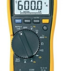
Fluke 1587 T Offers
Features
True RMS voltage and current for accurate measurements
Digital display counts of 6000
Auto-range and manual range for easy testing
Selectable filter for accurate voltage and frequency measurements on motor
drives
Special remote control probe for easy and safe measurements
Auto-discharge of capacitive voltage for added user protection
Live circuit detection prevents insulation test if voltage > 30 V is detected for
added user protection
Auto power off to save batteries
Large display with backlight
Input Alert to warn for incorrect connections
Continuity
6 Tips for effective insulation testing
1
Disconnect any electronic devices like motor drives, PLC’s, transmitters, etc. before performing insulation testing. Electronics can be damaged by applying higher than normal voltage.
2
The effect of temperature should be considered – it is recommended that tests be performed at a standard conductor temperature of 20 °C (68 °F) or that a temperature baseline is established while compensating future readings by using a DMM with a probe or an infrared thermometer.
3
Select a test voltage appropriate for the insulation being tested. The objective is to stress the insulation but not to over-stress it. When in doubt, use a lower test voltage. It’s usually appropriate to test insulation at twice the voltage it normally sees: for example 460 V to 600 V rated equipment is often tested at 1000 V.
4
When using an insulation tester, leave the leads connected when you stop the test. The insulation tester can discharge any residual test voltage.
5
Conductors that are close to each other have a normal capacitance. This will cause an insulation resistance reading to start low and increase steadily until it stabilizes. This type of increase is normal, but if the reading jumps violently down and up again this indicates arcing.
6
Although the current is tightly limited, an insulation tester can generate sparks and minor but painful burns. The unexpected surprise can cause an operator to jerk away. As always, work away from live systems and use safe work practices when working overhead.
Insulation Resistance Testing SolutionsFluke 1587 T Offers
Features
True RMS voltage and current for accurate measurements
Digital display counts of 6000
Auto-range and manual range for easy testing
Selectable filter for accurate voltage and frequency measurements on motor
drives
Special remote control probe for easy and safe measurements
Auto-discharge of capacitive voltage for added user protection
Live circuit detection prevents insulation test if voltage > 30 V is detected for
added user protection
Auto power off to save batteries
Large display with backlight
Input Alert to warn for incorrect connections
Continuity
6 Tips for effective insulation testing
1
Disconnect any electronic devices like motor drives, PLC’s, transmitters, etc. before performing insulation testing. Electronics can be damaged by applying higher than normal voltage.
2
The effect of temperature should be considered – it is recommended that tests be performed at a standard conductor temperature of 20 °C (68 °F) or that a temperature baseline is established while compensating future readings by using a DMM with a probe or an infrared thermometer.
3
Select a test voltage appropriate for the insulation being tested. The objective is to stress the insulation but not to over-stress it. When in doubt, use a lower test voltage. It’s usually appropriate to test insulation at twice the voltage it normally sees: for example 460 V to 600 V rated equipment is often tested at 1000 V.
4
When using an insulation tester, leave the leads connected when you stop the test. The insulation tester can discharge any residual test voltage.
5
Conductors that are close to each other have a normal capacitance. This will cause an insulation resistance reading to start low and increase steadily until it stabilizes. This type of increase is normal, but if the reading jumps violently down and up again this indicates arcing.
6
Although the current is tightly limited, an insulation tester can generate sparks and minor but painful burns. The unexpected surprise can cause an operator to jerk away. As always, work away from live systems and use safe work practices when working overhead.
Insulation Resistance Testing Solutions
Fluke 1587 T Specifications
Insulation Specifications
Measurement Range
0.01 to 100 MΩ
Test Voltages
50 V, 100 V
Accuracy: + 20%, -0%
Insulation Test Current
1 mA nominal
Auto Discharge
Discharge time < 0.5 s for C = 1 µF or less
Maximum Capacitive Load
Up to 1 µF load
Multimeter Specifications
Voltage DC
Maximum: 1000 V
Maximum Resolution: 1 mV
Accuracy: ± (0.09% + 2)
Voltage AC
Maximum: 1000 V
Maximum Resolution: 0.1 mV
Accuracy: ± (2% + 3)
Current DC
Maximum: 400 mA
Maximum Resolution: 0.01 mA
Accuracy: ± (0.2% + 2)
Current AC
Maximum: 400 mA
Maximum Resolution: 0.01 mA
Accuracy: ± (1.5% + 2)
Resistance
Maximum: 50.0 MΩ
Maximum Resolution: 0.1 Ω
Accuracy: ± (0.9% + 2)
Capacitance
Maximum: 9999 µF
Maximum Resolution: 1 nF
Accuracy: ± (1.2% + 2)
Frequency
Maximum: 99.99 kHz
Maximum Resolution: 0.01 Hz
Accuracy: ± (0.1% + 1)
Temperature
Maximum: -40 to 998.6°F (-40 to 537°C)
Maximum Resolution: 32.1°F (0.1°C)
Accuracy: ± (1% + 10)
General Specifications
Temperature
Operating: -4 to 131°F (-20 to 55°C)
Storage: -40 to 140°F (-40 to 60°C)
Power Supply
4 x AA Batteries (NEDA 15A or IEC LR6)
Battery Life
Meter: 1000 hrs
Insulation Test: > 1000 tests
Dimensions
8 x 4 x 2″ (203 x 100 x 50 mm)
Weight
1.2 lbs (0.55 kg)
Click here for complete specifications on the Fluke 1587 T
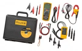
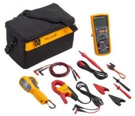
What’s included with the Fluke 1587 T
Insulation Multimeter
Remote Test Probe
K-Type Thermocouple Probe
Silicone Test Lead Set
Alligator Clip Set
Carrying Case
Two in one tools
Stand-alone tools
Insulation test features
1587 FC
1577
1503
1507
1550C
1555
Test voltages
50 V, 100 V, 250 V, 500 V, 1000 V
500 V, 1000 V
500 V, 1000 V
50 V, 100 V, 250 V, 500 V, 1000 V
250 V to 5000 V
250 V to 10,000 V
Insulation resistance range
0.01 MΩ to 2 GΩ
0.01 MΩ to 600 GΩ
0.01 MΩ to 2000 GΩ
0.01 MΩ to 10 GΩ
250 kΩ to 1 TΩ
250 kΩ to 2 TΩ
PI/DAR
Auto discharge
Timed ramp test (Breakdown)
Pass/fail comparison
Est. # of IRT tests
1000
1000
2000
2000
Various
Various
Voltage > 30 V warning
Memory
With Fluke Connect App
Remote test probe
Lo ohms/earth-bond continuity
200 mA source (10 mΩ resolution)
200 mA source (10 mΩ resolution)
Display
Digital LCD
Digital LCD
Digital LCD
Digital LCD
Digital LCD/ analog display
Digital LCD/ analog display
Hold/lock
Multimeter features
AC/DC volts
Note: Not all product features and specifications are listed in this table. For more complete information, see individual product data sheets.
Footnotes:
1. Function useful for checking connections and motor windings. Also useful for users who are required to perform earth-bond continuity measurements during installation testing.
2. Filter for variable-speed motor drive measurements.
Current
Resistance
Continuity beeper
Temperature (contact)
Lo-pass filter2
Capacitance
Diode test
Frequency
MIN/MAX
Other features
Backlight
Software
Fluke Connect compatible
FlukeView® Forms Basic
Fluke View® Forms Basic
Battery
4 AA (NEDA 15A or IEC LR6)
4 AA (NEDA 15A or IEC LR6)
4 AA (NEDA 15A or IEC LR6)
4 AA (NEDA 15A or IEC LR6)
Rechargeable
Rechargeable
Find out more about insulation testing







There are no reviews yet.