


Fluke 124B OffersCompact and rugged, this oscilloscope is ideal for industrial electrical and electro-mechanical equipment troubleshooting and maintenance applications. Features innovative functions that help technicians troubleshoot faster for quicker results and to keep their systems running smoothly. Additionally, triggering displays waveforms without having to adjust amplitude, timebase, and trigger settings.
Features
Key measurements: Voltage and power waveforms
Automatically capture, view and analyze complex waveforms: Fluke Connect and View™ triggering automatically displays waveforms without having to adjust amplitude, timebase and trigger settings, while Intellaset™ technology analyzes the signal and automatically displays critical numerical readings, making troubleshooting faster than ever
View data locally on the instrument, or via Fluke Connect mobile app
Dual-input digital oscilloscope and multimeter
40 MHz oscilloscope bandwidth
Two 5000-count true-rms digital multimeters
Connect-and-View trigger simplicity for hands-off operation
IntellaSet technology automatically and intelligently adjusts numerical readout based on the measured signal
Dual-input waveform and meter reading recorder for trending data over extended periods
Recorder Event Detect captures elusive intermittent signals on repetitive waveforms up to 4 kHz
Shielded test leads for oscilloscope, resistance and continuity measurements
Resistance, continuity, diode and capacitance meter measurements
Power measurements (W, VA, VAR, PF, DPF, Hz)
Save or recall data and instrument setups
Store instrument setups defined by a test sequence for routine maintenance or most often used test procedures
External optically isolated USB interface to transfer, archive and analyze scope or meter data
Optional WiFi adapter connected to internal USB port to wirelessly transfer information to the PC, laptop or Fluke Connect mobile app
Rugged design to withstand 3 g Vibration, 30 g shock, and rated IP51 according to EN/IEC60529
Highest safety rating in the industry: safety rated for CAT IV 600 V
Connect-and-View triggering for an instant, stable display
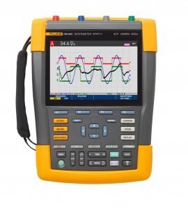
Oscilloscope users know how difficult triggering can be. Using the wrong settings can lead to unstable waveform captures, and sometimes the wrong measurement data. This instrument’s unique Connect-andView triggering technology recognizes signal patterns and automatically sets up the correct triggering to provide a stable, reliable, and repeatable display. Connect-and-View triggering is designed to work with virtually any signal, including motor drives and control signals – without adjusting parameters, or even touching a button. Signal changes are instantly recognized and settings are automatically adjusted, providing a stable display even when measuring multiple test points in quick succession.
IntellaSet/AutoReading
The Auto Readings function with Fluke IntellaSet technology uses proprietary algorithms to intelligently analyze the measured waveform and automatically displays the most appropriate numerical measurements on the screen, so you can get the data you need easier than ever before. As an example, when the measured waveform is a line voltage signal, the Vrms and Hz readings are automatically displayed, whereas if the measured waveform is a square wave, the Vpeak-peak, and Hz readings are automatically displayed. Using IntellaSet technology in conjunction with Connect-and-View automatic triggering you can be sure you’re seeing not only the correct waveform but the appropriate numerical reading as well. All without touching a button.
Industrial equipment needs a reliable power supply to operate properly, use the dual input to obtain key power measurements
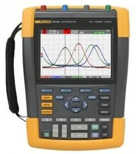
For single-phase or 3-phase balanced systems, the dual inputs of the Industrial ScopeMeter 120B Series can measure AC+DC RMS voltage on channel A and AC+DC RMS current on channel B. This oscilloscope can then calculate; frequency, phase angle, active power (kW), reactive power (VA or var), power factor (PF), or displacement power factor (DPF) and can also calculate the power values for a 3-phase system where all phases have equal voltage and currents. This applies to both balanced systems and resistive loads.
One test lead to measure multiple electrical parameters
High-frequency waveform, meter, capacitance, and resistance measurements as well as continuity checks are all covered by a single set of shielded test leads. No time is wasted finding or swapping leads.
Fluke Connect mobile app compatibility
Automated industrial machinery is harder than ever to troubleshoot. It’s not enough to just know where you have to test, you also have to know what to look for and that can be hard without baseline measurement data or access to subject matter experts. This Fluke Connect Assets wireless system of software and wireless test tools enables technicians to reduce maintenance costs and increase uptime with accurate equipment records and maintenance data that is easy to interpret, and share. Compare and contrast test point measurement data and trends so you can better understand signal characteristics and changes over time. And, by storing maintenance data on the Fluke Cloud you can enable team members to access it from wherever and whenever they need to so you can get advice or approvals in the field and get your systems up and running faster than ever before.
Use the comprehensive recorder modes to help find intermittent faults with ease
The toughest faults to find are those that happen only once in a while-intermittent event. They can be caused by bad connections, dust, dirt, corrosion, or simply broken wiring or connectors. Other factors, like line outages and sags or the starting and stopping of a motor, can also cause intermittent events resulting in equipment shutdowns. When these events happen, you may not be around to see them. But, your Fluke ScopeMeter Test Tool will. You can either plot the minimum and maximum peak measurement values or record the waveform trace. And, with expandable micro SD memory, recording sessions can be done for up to 14 days. This recorder is even more powerful with the addition of Recorder Event Detect, which makes detecting and logging intermittent faults easier than ever. Just set a threshold on a meter reading or scope trace and deviations are tagged as unique events. You no longer need to search through masses of data to pinpoint faults, and can quickly step from one tagged event to the next, while still having access to the full data set.
Applications
Ideal for industrial electrical and electro-mechanical equipment troubleshooting and maintenance applicationsFluke 124B OffersCompact and rugged, this oscilloscope is ideal for industrial electrical and electro-mechanical equipment troubleshooting and maintenance applications. Features innovative functions that help technicians troubleshoot faster for quicker results and to keep their systems running smoothly. Additionally, triggering displays waveforms without having to adjust amplitude, timebase, and trigger settings.
Features
Key measurements: Voltage and power waveforms
Automatically capture, view and analyze complex waveforms: Fluke Connect and View™ triggering automatically displays waveforms without having to adjust amplitude, timebase and trigger settings, while Intellaset™ technology analyzes the signal and automatically displays critical numerical readings, making troubleshooting faster than ever
View data locally on the instrument, or via Fluke Connect mobile app
Dual-input digital oscilloscope and multimeter
40 MHz oscilloscope bandwidth
Two 5000-count true-rms digital multimeters
Connect-and-View trigger simplicity for hands-off operation
IntellaSet technology automatically and intelligently adjusts numerical readout based on the measured signal
Dual-input waveform and meter reading recorder for trending data over extended periods
Recorder Event Detect captures elusive intermittent signals on repetitive waveforms up to 4 kHz
Shielded test leads for oscilloscope, resistance and continuity measurements
Resistance, continuity, diode and capacitance meter measurements
Power measurements (W, VA, VAR, PF, DPF, Hz)
Save or recall data and instrument setups
Store instrument setups defined by a test sequence for routine maintenance or most often used test procedures
External optically isolated USB interface to transfer, archive and analyze scope or meter data
Optional WiFi adapter connected to internal USB port to wirelessly transfer information to the PC, laptop or Fluke Connect mobile app
Rugged design to withstand 3 g Vibration, 30 g shock, and rated IP51 according to EN/IEC60529
Highest safety rating in the industry: safety rated for CAT IV 600 V
Connect-and-View triggering for an instant, stable display
Oscilloscope users know how difficult triggering can be. Using the wrong settings can lead to unstable waveform captures, and sometimes the wrong measurement data. This instrument’s unique Connect-andView triggering technology recognizes signal patterns and automatically sets up the correct triggering to provide a stable, reliable, and repeatable display. Connect-and-View triggering is designed to work with virtually any signal, including motor drives and control signals – without adjusting parameters, or even touching a button. Signal changes are instantly recognized and settings are automatically adjusted, providing a stable display even when measuring multiple test points in quick succession.
IntellaSet/AutoReading
The Auto Readings function with Fluke IntellaSet technology uses proprietary algorithms to intelligently analyze the measured waveform and automatically displays the most appropriate numerical measurements on the screen, so you can get the data you need easier than ever before. As an example, when the measured waveform is a line voltage signal, the Vrms and Hz readings are automatically displayed, whereas if the measured waveform is a square wave, the Vpeak-peak, and Hz readings are automatically displayed. Using IntellaSet technology in conjunction with Connect-and-View automatic triggering you can be sure you’re seeing not only the correct waveform but the appropriate numerical reading as well. All without touching a button.
Industrial equipment needs a reliable power supply to operate properly, use the dual input to obtain key power measurements
For single-phase or 3-phase balanced systems, the dual inputs of the Industrial ScopeMeter 120B Series can measure AC+DC RMS voltage on channel A and AC+DC RMS current on channel B. This oscilloscope can then calculate; frequency, phase angle, active power (kW), reactive power (VA or var), power factor (PF), or displacement power factor (DPF) and can also calculate the power values for a 3-phase system where all phases have equal voltage and currents. This applies to both balanced systems and resistive loads.
One test lead to measure multiple electrical parameters
High-frequency waveform, meter, capacitance, and resistance measurements as well as continuity checks are all covered by a single set of shielded test leads. No time is wasted finding or swapping leads.
Fluke Connect mobile app compatibility
Automated industrial machinery is harder than ever to troubleshoot. It’s not enough to just know where you have to test, you also have to know what to look for and that can be hard without baseline measurement data or access to subject matter experts. This Fluke Connect Assets wireless system of software and wireless test tools enables technicians to reduce maintenance costs and increase uptime with accurate equipment records and maintenance data that is easy to interpret, and share. Compare and contrast test point measurement data and trends so you can better understand signal characteristics and changes over time. And, by storing maintenance data on the Fluke Cloud you can enable team members to access it from wherever and whenever they need to so you can get advice or approvals in the field and get your systems up and running faster than ever before.
Use the comprehensive recorder modes to help find intermittent faults with ease
The toughest faults to find are those that happen only once in a while-intermittent event. They can be caused by bad connections, dust, dirt, corrosion, or simply broken wiring or connectors. Other factors, like line outages and sags or the starting and stopping of a motor, can also cause intermittent events resulting in equipment shutdowns. When these events happen, you may not be around to see them. But, your Fluke ScopeMeter Test Tool will. You can either plot the minimum and maximum peak measurement values or record the waveform trace. And, with expandable micro SD memory, recording sessions can be done for up to 14 days. This recorder is even more powerful with the addition of Recorder Event Detect, which makes detecting and logging intermittent faults easier than ever. Just set a threshold on a meter reading or scope trace and deviations are tagged as unique events. You no longer need to search through masses of data to pinpoint faults, and can quickly step from one tagged event to the next, while still having access to the full data set.
Applications
Ideal for industrial electrical and electro-mechanical equipment troubleshooting and maintenance applications
Fluke 124B Specifications
Oscilloscope Mode (Vertical)
Frequency Response – DC Coupled
Without probes and test leads (with BB120): DC to 40 MHz (-3 dB)
With STL120-IV 1:1 shielded test leads: DC to 12.5 MHz (-3 dB), DC to 20 MHz (-6 dB)
With VP41 10:1 probe: DC to 40 MHz (-3 dB)
Frequency Response – AC Coupled (LF Roll Off)
Without probes and test leads: <10 Hz (-3 dB)With STL120-IV 1:1 shielded test leads: <10 Hz (-3 dB)With VP41 10:1 probe: <10 Hz (-3 dB)
Rise Time, Excluding Probes, Test Leads
<8.75 ns
Input Impedance
Without probes and test leads: 1 MΩ/20 pFWith BB120: 1 MΩ/24 pFWith STL120-IV 1:1 shielded test leads: 1 MΩ/230 pFWith VP41 10:1 probe: 5 MΩ/15.5 pF
Sensitivity
5 mV to 200 V/div
Analog Bandwidth Limiter
10 kHz
Display Modes
A, -A, B, -B
Maximum Input Voltage A and B
Direct, with test leads, or with VP41 probe: 600 Vrms CAT IV, 750 Vrms maximum voltageWith BB120: 600 Vrms
Maximum Floating Voltage, from any Terminal to Ground
600 Vrms CAT IV, 750 Vrms up to 400 Hz
Oscilloscope Mode (Horizontal)
Scope Modes
Normal, single, roll
Ranges (Normal)
Equivalent sampling: 10 ns to 500 ns/divReal time sampling: 1 μs to 5 s/divSingle (real time): 1 μs to 5 s/divRoll (real time): 1 s to 60 s/div
Sampling Rate (for Both Channels Simultaneously)
Equivalent sampling (repetitive signals): up to 4 GS/sReal time sampling 1 μs to 60 s/div: 40 MS/s
Trigger
Screen Update
Free run, on trigger
Source
A, B
Sensitivity A and B
At DC to 5 MHz: 0.5 divisions or 5 mVAt 40 MHz: 1.5 divisionsAt 60 MHz: 4 divisions
Slope
Positive, negative
Advanced Scope Functions
Display Modes
Normal: Captures up to 25 ns glitches and displays analog-like persistence waveformSmooth: Suppresses noise from a waveformGlitch off: Does not capture glitches between samplesEnvelope: Records and displays the minimum and maximum of waveforms over time
Auto Set (Connect-and-View)
Continuous fully automatic adjustments of amplitude, time base, trigger levels, trigger gap, and hold-off. Manual override by user adjustment of amplitude, time base, or trigger level
Input A and B
DC Voltage (V DC)
Ranges: 500 mV, 5, 50, 500, 750 VAccuracy: ±(0.5% +5 counts)Common mode rejection (CMRR): >100 dB at DC, >60 dB at 50, 60, or 400 Hz
Full scale reading: 5000 counts
True RMS Voltages (V AC and V AC+DC)
Ranges: 500 mV, 5, 50, 500, 750 V
Accuracy for 5 to 100% of range (DC coupled)
DC to 60 Hz (V AC + DC): ±(1% +10 counts)
1 to 60 Hz (V AC): ±(1% +10 counts)
Accuracy for 5 to 100% of range (AC or DC coupled): 60 Hz to 20 kHz: ±(2.5% +15 counts)
DC rejection (only V AC): >50 dB
Common mode rejection (CMRR): >100 dB at DC; >60 dB at 50, 60, or 400 Hz
Full scale reading: 5000 counts, reading is independent of any signal crest factor
Peak
Modes: Maximum peak, minimum peak, peak-to-peak
Ranges: 500 mV, 5, 50, 500, 2200 V
Accuracy: Maximum peak or minimum peak: 5% of full scale; peak-to-peak: 10% of full scale
Full scale reading: 500 counts
Frequency
Ranges: 1, 10, 100 Hz, 1, 10, 100 kHz, 1, 10, and 70 MHz
Frequency range: 15 Hz (1 Hz) to 50 MHz in continuous autoset
Accuracy at 1 Hz to 1 MHz: ±(0.5% +2 counts)
Full scale reading: 10,000 counts
RPM
Maximum reading: 50 kRPM
Accuracy: ±(0.5% +2 counts)
Duty Cycle
Range: 2 to 98%
Frequency range: 15 Hz (1 Hz) to 30 MHz in continuous autoset
Pulse Width
Frequency range: 15 Hz (1 Hz) to 30 MHz in continuous autoset
Full scale reading: 1000 counts
Amperes
With current clamp
Ranges: same as V DC, V AC, V AC+DC, or peak
Scale factors: 0.1, 1, 10, 100, 400 mV/A, 1 V/A, 10 mV/mA
Accuracy: same as V DC, V AC, V AC+DC, or peak (add current clamp uncertainty)
Decibel
0 dBV: 1 V
0 dBm (600/50 Ω): 1 mW referenced to 600 or 50 Ω
dB on V DC, V AC, or V AC+DC
Full scale reading; 1000 counts
Crest Factor
Range: 1 to 10
Full scale reading: 90 counts
Phase
Modes: A to B, B to A
Range: 0 to 359°
Resolution: 1°
Vpwm
Purpose: To measure on pulse width modulated signals, like motor drive inverter outputs
Principle: Readings show the effective voltage based on the average value of samples over a whole number of periods of the fundamental frequency
Accuracy: As Vrms for sine wave signals
Input A to Common
Ohm
Ranges: 500 Ω, 5, 50, 500 kΩ, 5, 30 MΩ
Accuracy: ±(0.6% +5 counts) 50 Ω ±(2% +20 counts)
Full scale reading: 50 Ω to 5 MΩ – 5000 counts; 30 MΩ – 3000 counts
Measurement current: 0.5 mA to 50 nA, decreases with increasing ranges
Open circuit voltage: <4 V Common Continuity (Cont) Beep: <(30 Ω ±5 Ω) in 50 Ω rangeMeasurement current: 0.5 mADetection of shorts of: ≥1 ms Common Diode Measurement voltage: At 0.5 mA: >2.8 V
At open circuit: <4 VMeasurement current: 0.5 mAPolarity: + on input A, - on COM Capacitance (CAP) Ranges: 50, 500 nF, 5, 50, 500 μFFull scale reading: 5000 countsMeasurement current: 500 nA to 0.5 mA, increases with increasing ranges Advanced Meter Functions Zero Set Set actual value to reference AutoHold (on A) Captures and freezes a stable measurement result. Beeps when stable. AutoHold works on the main meter reading, with thresholds of 1 Vpp for AC signals and 100 mV for DC signals Fixed Decimal Point Activated by using attenuation keys Cursor Readout Sources A, B Single Vertical Line Average, minimum and maximum readoutAverage, minimum, maximum and time from start of readout (in ROLL mode; instrument in HOLD)Minimum, maximum and time from start of readout (in RECORDER mode; instrument in HOLD)Harmonics values in POWER QUALITY mode Dual Vertical Lines Peak-peak, time distance and reciprocal time distance readoutAverage, minimum, maximum and time distance readout (in ROLL mode; instrument in HOLD) Dual Horizontal Lines High, low and peak-peak readout Rise or Fall Time Transition time, 0%-level and 100%-level readout (manual or auto leveling; auto leveling only possible in single channel mode) Accuracy As oscilloscope accuracy Recorder Meter Readings Measurement speed: Maximum 2 measurementsRecord size (minimum, maximum, average): 2 M readings for 1 channelRecorded time span: 2 weeksMaximum number of events: 1024 Waveform Record Maximum sample rate: 400 K samplesSize internal memory: 400 M samples recorded timeSpan internal memory: 15 minutes at 500 μs/div - 11 hours at 20 ms/divRecord size SD card: 1.5 G samplesRecorded time span SD card: 11 hours at 500 μs/div - 14 days at 20 ms/divMaximum number of events: 64 General Specifications Waveform Display Vertical: 10 div of 40 pixelsHorizontal: 12 div of 40 pixels Maximum Input Voltage A and B Direct on input or with leads: 600 Vrms CAT IV for deratingWith banana-to BNC adapter BB120: 600 Vrms for deratingMaximum floating voltage from any terminal to ground: 600 Vrms CAT IV, 750 Vrms up to 400 Hz Display Type: 5.7" color active martrix TFTResolution: 640 x 480 Interface Optically isolated: Transfer screen copies (bitmaps), settings and dataUSB to PC/laptop: OC4USB optically isolated USB adapter/cable, (optional), using FlukeView® software for Windows® Wireless Radio with Adapter Frequency range: 2412 to 2462 MHzOutput power: <100 mW Environmental MIL-PRF-28800F, Class 2 Temperature Battery operation: 32 to 104°F (0 to 40°C)Power adapter operation: 32 to 122°F (0 to 50°C)Storage: -4 to 140°F (-20 to 60°C) non-condensing Humidity (Operating) At 32 to 50°F (0 to 10°C): non-condensingAt 50 to 86°F (10 to 30°C): 95%At 86 to 104°F (30 to 40°C): 75%At 104 to 122°F (40 to 50°C): 45% Altitude Operating at 10,000' (3 km): CAT III 600 VOperating at 6600' (2 km): CAT IV 600 VStorage: 40,000' (12 km) EMC Electromagnetic Compatibility USA (FCC): 47 CFR 15 subpart B (this product is considered an exempt device per clause 15.103) Enclosure Protection IP51, ref: EN/IEC60529 Safety General: IEC 61010-1: Pollution Degree 2Measurement: IEC 61010-2-033: CAT IV 600 V/CAT III 750 V Memory Internal memory can store 20 data sets (screen waveform and setup)Micro SD card slot with optional SD card (maximum size of 32 GB) Power External: Via power adapter BC430Input voltage: 10 to 21 V DC Consumption: 5 W typicalInput connector: 5 mm jackInternal: Via battery pack BP290Battery power: Rechargeable Li-Ion 10.8 VOperating time: 7 hours with 50 % backlight brightnessCharging time: 4 hours with test tool off, 7 hours with test tool onAllowable ambient temperature: 32 to 104°F (0 to 40°C) during charging Dimensions 10.2 x 5.2 x 2.15" (259 x 132 x 55 mm) Weight 3.2 lbs (1.4 kg) including battery packClick here for complete specifications on the Fluke 124B What's included with the Fluke 124B Oscilloscope 2 x Shielded Test Leads with Ground Leads Test Lead Hook Clips Banana to BNC Adapter Voltage Probe USB Angled Adapter WiFi USB Adapter Li-Ion Battery Pack Charger/Power AdapterSee it. Save it. Share it. All the facts, right in the field.Fluke engineers have delivered an innovative mobile platform and tool that helps solve everyday problems, allowing you to instantly document measurements, retrieve historical data, and share live measurements with your team. All handled by the Android™ or iOS smart phone you already carry.Fluke Connect with ShareLive™ video call is the only wireless measurement system that lets you stay in contact with your entire team without leaving the field. The Fluke Connect mobile app is works with over 20 different Fluke products - the largest suite of connected test tools in the world.Make the best decisions faster than ever before by viewing temperature, mechanical, electrical and vibration measurements for each equipment asset in one place. Get started saving time and increasing your productivity.Fluke Connect Features:TrendIt™ Graphs: Use graphing to show changes in measurements, allowing you to graph and show problems instantly.EquipmentLog™ History: Access equipment history building a database of equipment health and baselines with cloud backup.ShareLive™ Video Calls: Save, collaborate and share measurements instantly with your team anytime, from anywhere.AutoRecord™ Measurements: Instantly save measurements to your phone with Cloud backup.Fluke Cloud™ Storage: Securely access equipment records anywhere, anytime.Fluke Connect Benefits:Maximize uptimeMinimize maintenance costsBetter assessments with accurate recordsHigher efficiency with less walking around; no notebook and excel neededShare troubleshooting knowledge liveCreate and share helpful content in the fieldAccess to Fluke digital product manuals means no need to carry manuals in the fieldKeep organized manually entered measurements Webinar: EVSE Safety Maintenance with FlukeIn recent years, more people are opting for greener solutions to minimize environmental damage, which has led to an increased demand for environmentally safe solutions such as electric vehicles. Naturally, this has led to an increase in the installation of EV charging stations, but also the risks for technicians. In 2020, there were 126 fatal and 2200 non-fatal electrical injuries. Many of these are caused when technicians are exposed to hazardous voltage and arc faults that could cause shock and fire hazards due to a lack of understanding of proper EVSE installation and maintenance. Considering that EVSEs have a high rate of failure, estimated at 30 to 50% (SAE), reliability is essential when building EV infrastructure and gaining user acceptance.


There are no reviews yet.